


Arduino 315MHz RF Romote Module Kits
.jpg)
1、Transmitter Module 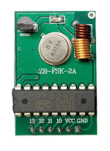
Technical Parameter
Frequency : 315Mhz
Working Voltage : 3~12V DC
Working current:3~45 (mA)
Frequency stability : 0.037ppm/℃
Temperature range:-10℃ ~ 70℃
Transmission rate : ≤10Kbps
Receiver Sensibility: -105dbm
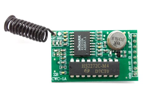
2、Receiver Module
Technical Parameters
Operating Voltage: DC 5V
Operating Frequency: 315 Mhz
Operating Current: 2.5mA
Quiescent Current: ≤5mA (5.0VDC)
Transmission rate:≤9.6Kbps
Receiver Sensitivity:-107dBm (50Ω)
Encoding: Fixed Code
Modulation: ASK-OOK
Operating Temperature: -30 ℃ ~ +80 ℃
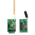
This 315MHz RF Module Kit including one 315MHz RF Receiver Module and one 315MHz RF Transmitter Module. This is the update version of this module kit, and the useage is the same as old versin as below:
This group RF modules contain: transmitter and receiver module, it can supply 4 channels to communicate, that's to say if you use them to control mini car, they have just four direction key.
This is transmitter module :
.jpg)
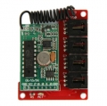
This is cooresponding receiver :
.jpg)
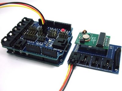
If you want to experiment these two module, only need to connect them to sensor shield by cables, for example you can connect the first channel of the transmitter module with the Arduino digital I/O pin 7, and the receiver to Arduino digital I/O pin 8 :
.jpg)
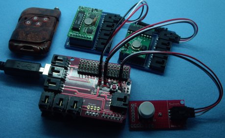
I wish once push one button, RF transmitter module send the signal, and after the receiver module receive the signal, light the Arduino's LED.
So you can connect Arduino digital I/O pin 2 with a digital button module, in order to receive the signal :
.jpg)
Copy the test code into Arduino:
int ledPin = 13;
int switchPin = 2;
int sendPin = 7;
int recvPin = 8;
int value = 0;
void setup() {
pinMode(switchPin, INPUT);
pinMode(recvPin, INPUT);
pinMode(ledPin, OUTPUT);
pinMode(sendPin, OUTPUT);
}
void loop() {
value = digitalRead(switchPin);
if (HIGH == value) {
digitalWrite(sendPin, HIGH);
} else {
digitalWrite(sendPin, LOW);
}
value = digitalRead(recvPin);
if (HIGH == value) {
digitalWrite(ledPin, HIGH);
} else {
digitalWrite(ledPin, LOW);
}
}
Once push one button, RF transmitter module send the signal, and receiver module receive the signal, at last light the LED of pin 13.

Join our newsletter today, to get latest product information and promotion code.
 |
 |
|

|