


LSM303DLHC+L3GD20 9DOF Sensor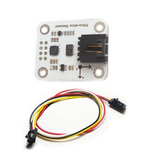
Introduction
This module is an inertial measurement unit (IMU) that packs an L3GD20 3-axis gyro and an LSM303DLHC 3-axis accelerometer and 3-axis magnetometer onto a small board. An I2C interface accesses nine independent rotation, acceleration, and magnetic measurements that can be used to calculate the sensor’s absolute orientation. This module includes board includes a voltage regulator and a level-shifting circuit that allows operation from 3.3V to 5.5 V, and the 0.1″ pin spacing safe header makes it easy to use with wires of standard 0.1″ female header. The TTL shifter allows a wide range of TTL input from 3.3V~12.0V. Before using this product, we therefore recommend careful reading of the L3GD20 datasheet and the LSM303DLHC datasheet.
The L3GD20 and the LSM303DLHC have many configurable options, including dynamically selectable sensitivities for the gyro, accelerometer, and magnetometer, as well as a choice of output data rates for each sensor. The two ICs can be accessed through a shared I2C/TWI interface, allowing all three sensors to be addressed individually via a single clock line and a single data line. The nine independent rotation, acceleration, and magnetic readings (sometimes called 9DOF) provide all the data needed to make an attitude and heading reference system (AHRS). With an appropriate algorithm, a microcontroller or computer can use the data to calculate the orientation of this board; the gyro can be used to very accurately track rotation on a short timescale, while the accelerometer and compass can help compensate for gyro drift over time by providing an absolute frame of reference. The respective axes of the two chips are aligned on the board to facilitate these sensor fusion calculations.
Specifications
1、Dimensions: 35 × 29 × 8 mm
2、Operating voltage: 3V to 5.5 V
3、Supply current: 10 mA
4、Output format (I2C):
Gyro: one 16-bit reading per axis
Accelerometer: one 12-bit reading (left-justified) per axis
Magnetometer: one 12-bit reading (right-justified) per axis
5、Sensitivity range (configurable):
Gyro: ±250, ±500, or ±2000°/s
Accelerometer: ±2, ±4, ±8, or ±16 g
Magnetometer: ±1.3, ±1.9, ±2.5, ±4.0, ±4.7, ±5.6, or ±8.1 gauss
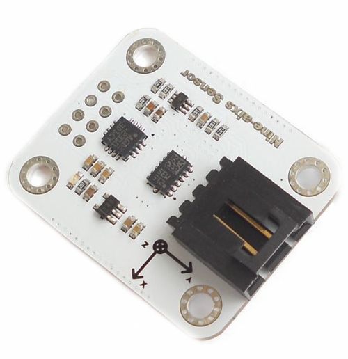
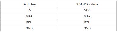
Connections
You could find the pin mark on the back of the module.
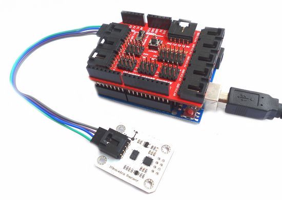
If you have Arduino Sensor Shield V7 , you could plug in and pay.
Join our newsletter today, to get latest product information and promotion code.
 |
 |
|

|