Product |
Shields
| 4-Channel Relay Shield, Support XBee
4-Channel Relay Shield, Support XBee

Description
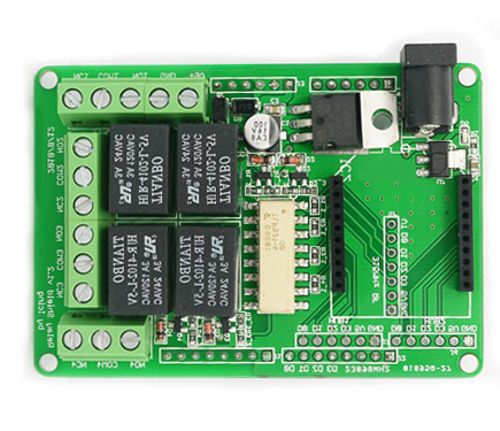
Arduino Relay Shield is a smart module with 4 mechanical relays providing an easy way for applications of voltage controlling from low to high. The max switching power could be DC90W or AC360VA. It could be directly controlled by Arduino through digital IOs with external 9v supply. With the RFBee socket and 315/433M RF module interface, the Relay shield could be remotely controlled, making it be easily used in robotics, industry control, smart house etc.
Compatible with UNO and Duemilanove
Please Note: For using with Arduino Uno, you need to be careful the pins on the Shield should not be touched with USB connector when they are connected.

Features
1、4 photo-coupled channel relay
2、Independent wiring in contact area for safety and reliability
3、Equipped with screw holes for easy installation
4、Light weight
5、Small form factor
6、Native Arduino compatibility
7、Extensible
1、4 photo-coupled channel relay
2、Independent wiring in contact area for safety and reliability
3、Equipped with screw holes for easy installation
4、Light weight
5、Small form factor
6、Native Arduino compatibility
7、Extensible
Key Specifications :
Contact Rating | 3A AC 120V / DC 24V |
Max Switching Voltage | AC 240V / DC 60V |
Max Switching Current | 5A |
Max Switching Power | AC 360VA / DC 90W |
Electrical Life (Min) | 100,000 Operations |
Mechanical Life (Min) | 10,000,000 Operations |
Safety Standard(relay) | UL cUL TUV CQC |
Coil Working Voltage | 9VDC |
Weight | 165g |
Working temperature | -30℃ to +85℃ |
Working temperature | 40% - 85% |
Please be very careful while operating high voltage circuits! You may get hurt (dead!) or hurt any connected equipment if you don't know what you're doing or if you make a mistake.
Schematic :
.jpg)
4 groups of channels for High voltage connection
COM1 Common pin
NC1 Normally Closed - NC1 is connected with COM1
when control port D0 is set low and disconnected when D0 is high
NO1 Normally Open - NO1 is disconnected from COM1
when control port D0 is set low and connected when D0 is high
Groups 2-4 are similar to Group 1, except for the control ports being D1-D3.
9v power supply connection
The function of the Terminal and the Jack is the same since they are internally connected, and you can choose either of them in needs.
IO controlling 4 on-board relays
D0-D3 4pins could be connected directly with Arduino pin number of 7-4, so that four relays could be easily controlled by the Arduino.
315M RF control interface
Together with pin of GND and 5v, they are the interface for 315M RFmodule to control the 4 relays remotely.
RFBee directly control interface
The 4 relays could be directly controlled by the RFBee through the 4 DIO ports of RFBee.
RFBee cascading control interface
As the RFBee has 12 DIO ports, 2more Relay Shield (8 more relays) could be controlled through one RFBee. HUB1 and HUB2 are the drawn-out ports of RFBee (4 as a group), which is connected to 315M RF interface of the cascading Relay Shield.
Usage :
1、With Arduino
Relay Shield could be directly controlled by Arduino.
Step1. Plug Relay Shield onto Arduino Duemilanove (or compatible) board;
Step2. Supply 9v DC power to Arduino;
Step3. Download the example code and run in Arduino IDE.
2、With 315M RF Module
Step1. Plug the Receiver onto the Relay Shield.
Step2: Supply the Relay Shield with 9v DC power.
Step3: Control the Transmitter.
Click to download the schematic diagram
Categories
Newsletter
Join our newsletter today, to get latest product information and promotion code.


