Product |
RF & Wireless
| 4KM Long Range RF Link Kits With Encoder And Decoder - 315Mhz
4KM Long Range RF Link Kits With Encoder And Decoder - 315Mhz.jpg)
This is 315Mhz version, if you need 433Mhz version, please click this link:
4KM Long Range RF Link Kits With Encoder And Decoder - 433Mhz
1、Transmitter Module

Features
This transmitter module uses SAW oscillator, with high frequency stability and small temperature drift. Even while touching the antenna with hand, there is no frequency offset. Its frequency error is very small, typically less than +/- 75kHz, which is far less than +/-500kHz frequency error of LC oscillator. The transmitter module size is small. It's operating voltage range is DC 3V-9V. So it has high transmit power and low power consumption. All contribute to stable performance.
It adopts SMD technology, and the most advanced SAW resonator (SAW) components for frequency stabilization. The circuit board (PCB) is made of material with the smallest dielectric loss. All the prodcuts has passed strict QC inspection before delivery.
Technical Parameters
Operating Voltage: DC 3V~9V (9V Recommend)
Operation Current: 100~150mA
Quiescent Current: ≤ 0.02uA
Modulation: ASK-OOK
Encoding Type: fixed code(PT2262)
Temperature range: -10℃ ~ +70℃
Transmission rate: <10Kbps
Transmit Distance: 4000 meters (in open area)
Oscillating Resistance: 4.7M
Size: 49 x 31 x 8mm
Frequency: 315Mhz
Operation Instruction
Transmitter module has 7 external interfaces.
+9V: DC +9V
GND: GND
D0/13, D1/12, D2/11, D3/10: data
ANT: Antenna
We recommend that 23cm soft wire or other hard metal of 23cm(such as the rod antenna) is connected to ANT as an antenna. If soft wire is used, it is recommended to straighten it to get the best results.
Address code: 8, which can be respectively set to vacant、high (H) and low (L). Address code can be self definition or changed according to your requirement. (Only if the transitter and the receiver have the same address, then they can communicate).
Data code: 4. The data code has only two states: high (H) and low (L). When one pin is set to high when the other pins are low, the corresponding output pin of receiver modules is high.
Please Note
Transmitter module has strict requirements to power supply. If power is short, transimission distance will be greatly shortened.
It is recommended to check whether the transmitter frequency and resistance matches with receiver's. If not, receiving distance will become short or even fails. Try to keep receiver module away from metal.
Pull out the antenna when launching pieces of the best, our commitment is fired from the launch of the antenna block all pulled out, the receiving antenna are all straight panels, firing block and Receiver are the height of 1.5m from the earth, Receiver only drive a light-emitting diode, in the flat, open, non-interference in the environment can reach the distance.
The transmit module is instantaneous transmit type. Transmit time should not be more than 3 seconds, and the interval should be more than 3 seconds. When distance between transimitter and receiver is small, power voltage should be reduced. For example, if the power voltage is 6V, transmission distance will reduce by a half.
If you want to take turns to remote control multiple channels, please connect as below :

If you just need one channel, you can directly connect Vcc with one interface of 10、11、12、13 as below :


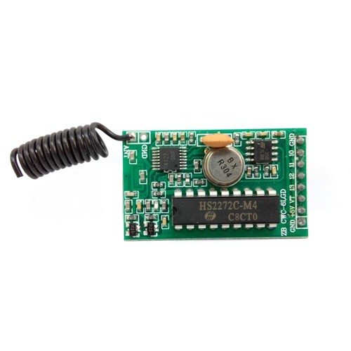
This is a Superheterodyne Receiver Module
Technical Parameters
Operating Voltage: DC 5V
Operating Frequency: 315 Mhz
Operating Current: 2.5mA
Quiescent Current: ≤8mA (5.0VDC)
Transmission rate: ≤9.6Kbps
Receiver Sensitivity: -107dBm (50Ω)
Encoding: Fixed Code
Modulation: ASK-OOK
Oscillating Resistance: 820K
Decoder: PT2272
Operating Temperature: -30 ℃ ~ +80 ℃
Dimensions: 41 x 24 x 8mm
Schematic Diagram

Pin Description

Receiver Module Test Circuit

In order to test whether the receiving modules work normally, give a DC 5V voltag between the VCC and GND interface of receiving module, and connect light emitting diode with pin 10, 11, 12, 13, 17 interface respectively.
When we press A button of trasmitter module, its corresponding pin 11 road LED will be light, until press the other button such as B key, pin 11 extinguish and pin 12 will be light.
Pin 17 interface is the effective decoding output port, no matter which button of the transmitter we push, it will become high level as long as decoding successfully, the transmitter stop transmitting immediately and it will extinguish.
Categories
Newsletter
Join our newsletter today, to get latest product information and promotion code.


